CURRENT COLLECTION OF SPACECRAFT AND PROPULSION COMPONENTS

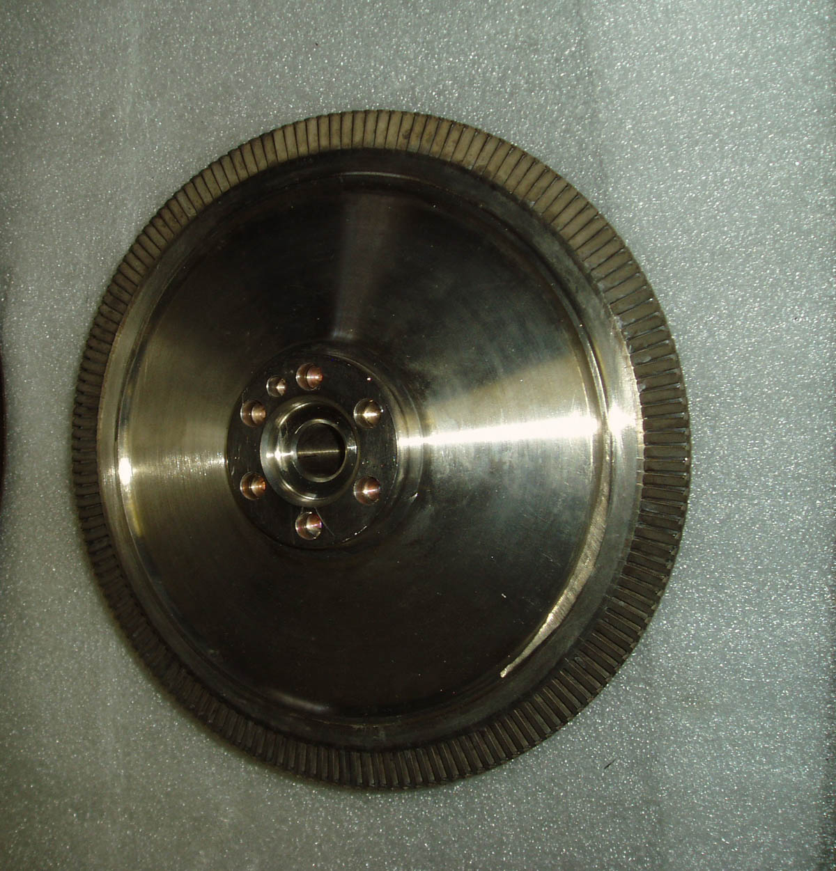
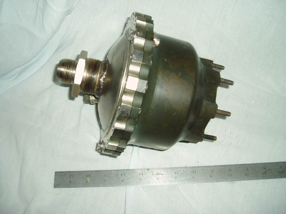
Atlas MA-5 Booster Inducer Impellers
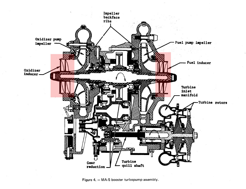
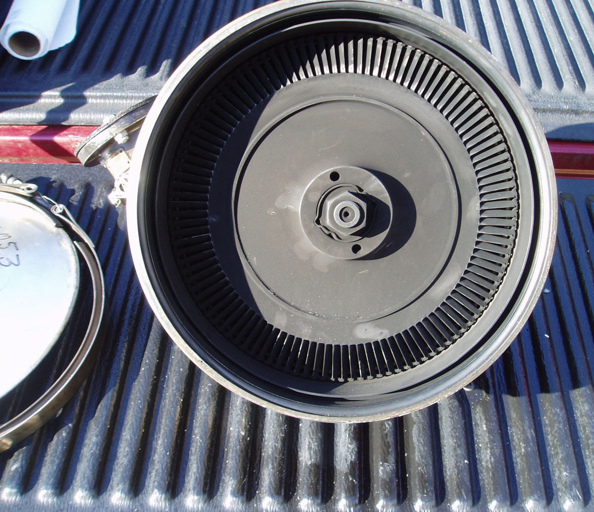
Atlas MA-5 Turbo Pump
ATLAS LAUNCH VEHICLE PROPULSION SYSTEM INDUCERS
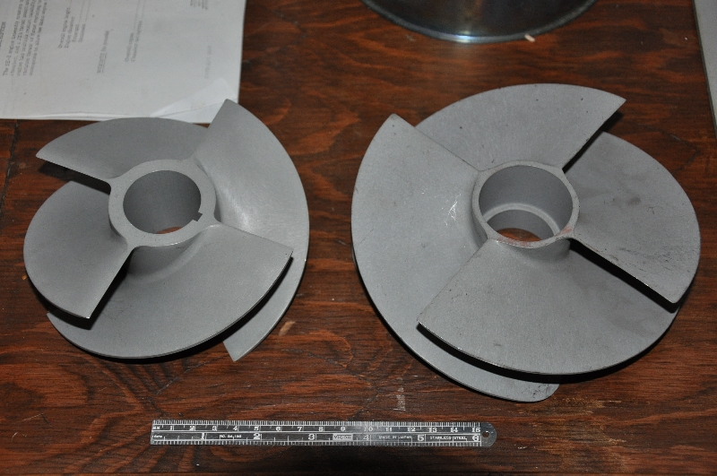
Atlas MA-5 turbopump inducers. Impeller on left is for the booster engine pump. The impeller on the right is for the sustainer pump. It is unknown at this time whether the impellers were for the oxidizer or fuel pumps. Inducers are used to compensate for relatively low inlet pressure supplied from the Atlas propellant tanks and eliminate cavitation in turbo-pumps designed for high compression ratios, insuring proper propellant head pressure and flow rate is supplied to each of the two Atlas MA-5 booster and single sustainer injector faces within the thrust chambers.
The impellers are fabricated from aluminum and are clear anodized. The choice of material, blade diameter, blade angle, leading edge shape and structural design parameters were crucial to ensuring the desired performance specifications and reliability were achieved.
The Atlas launch vehicle was developed to support Department of Defense (DOD) application as a delivery platform of Intercontinental Ballistic Missile (ICBM) nuclear warheads (in this configuration it received the military designation SM-65) and subsequently was adopted as a space launch system for Project Mercury, to place satellites in orbit and support deployment of lunar and interplanetary robotic exploration missions. Atlas derivatives continue to fly to this day, over 40 years after the initial booster was delivered to the USAF in 1957.
H-1 Gas Turbine Upper View
H-1 Gas Generator Label Plate
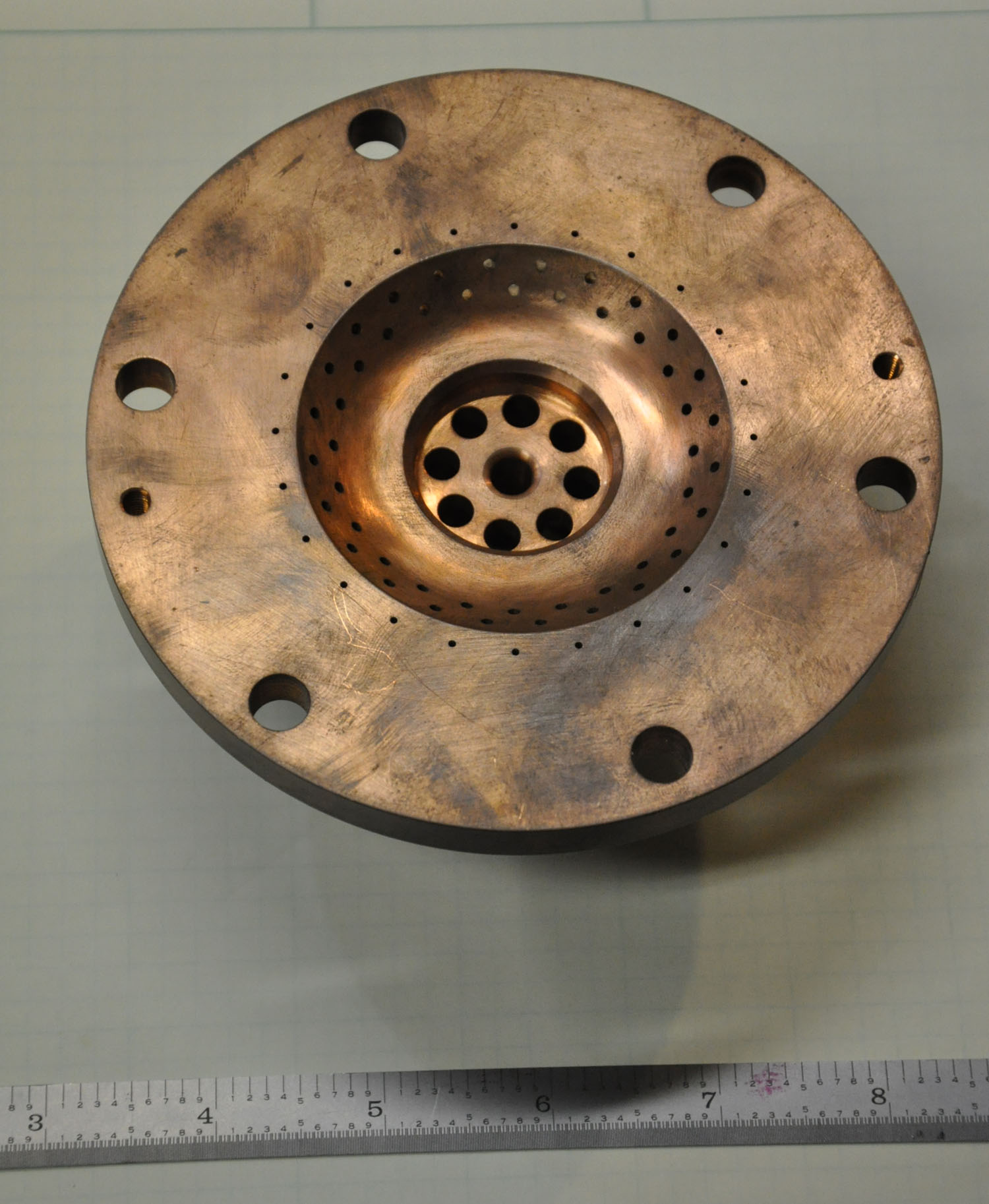
Liquid Propellant Gas Generator Injector (View 1)
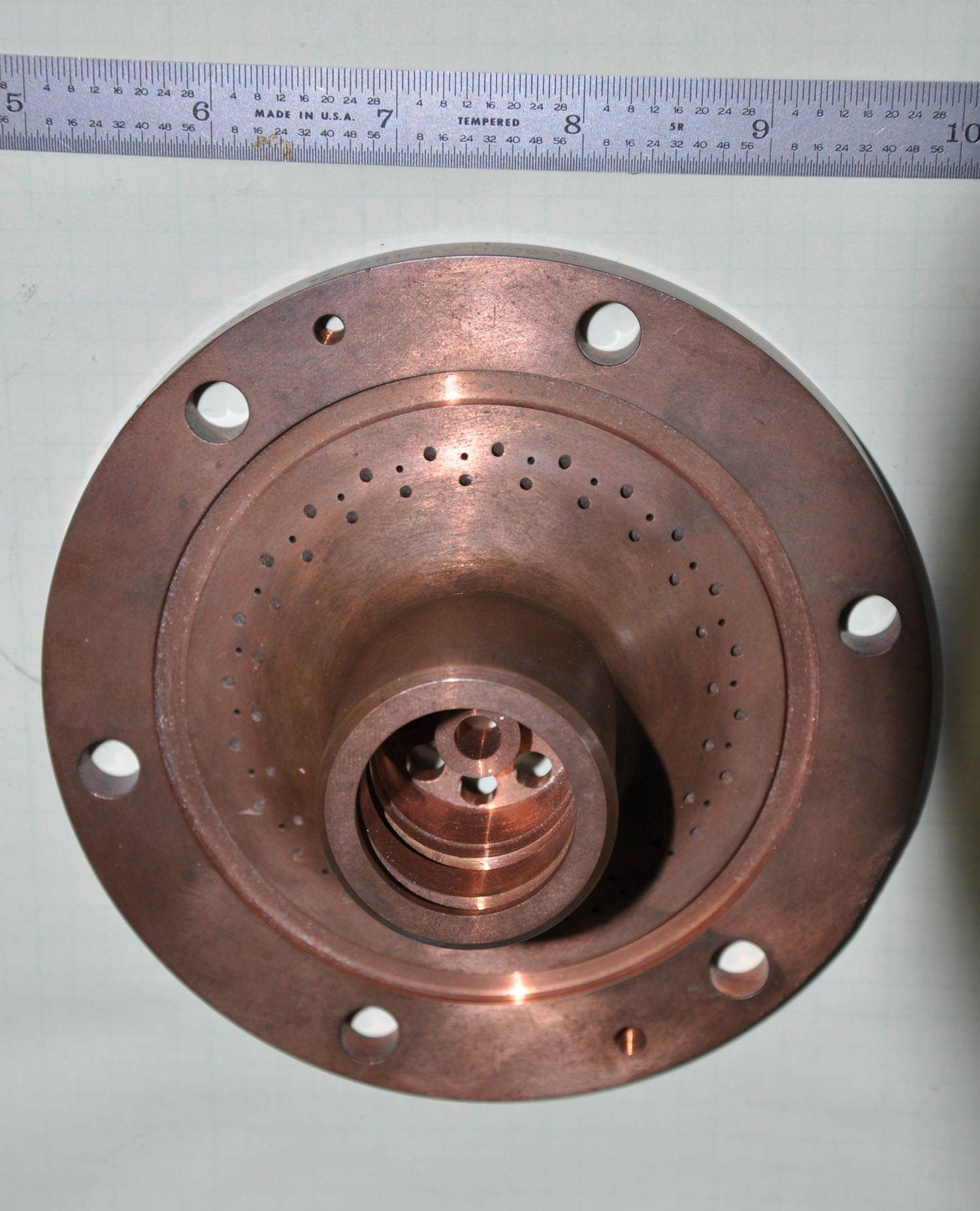
Liquid Propellant Gas Generator Injector (View 2)
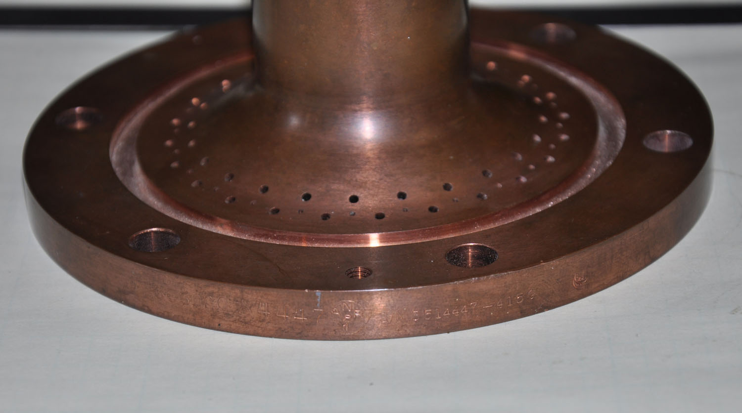
Liquid Propellant Gas Generator Injector (View 3)
H-1 Gas Generator Schematic
SATURN H-1 ROCKET ENGINE LIQUID PROPELLANT GAS GENERATOR
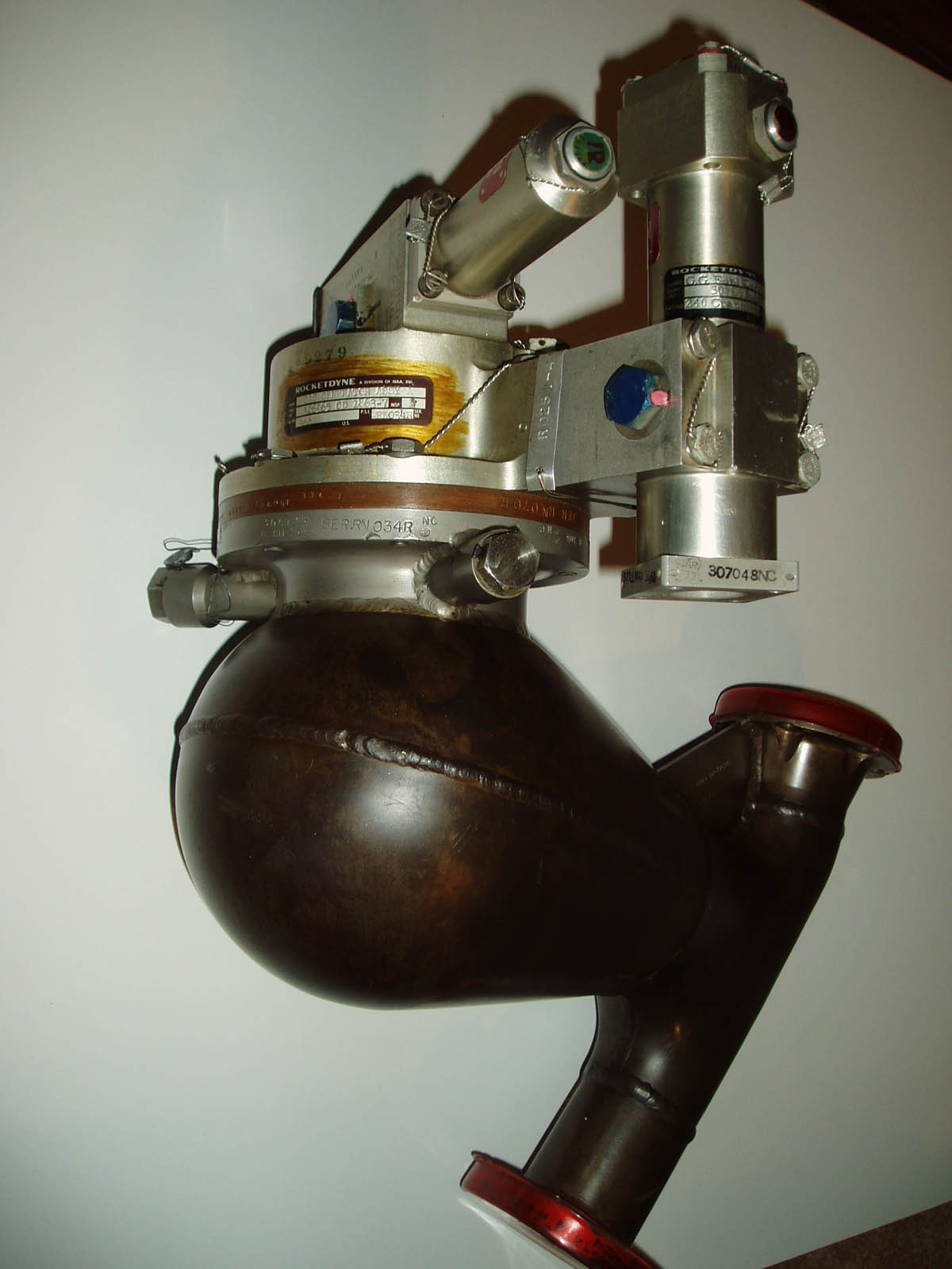
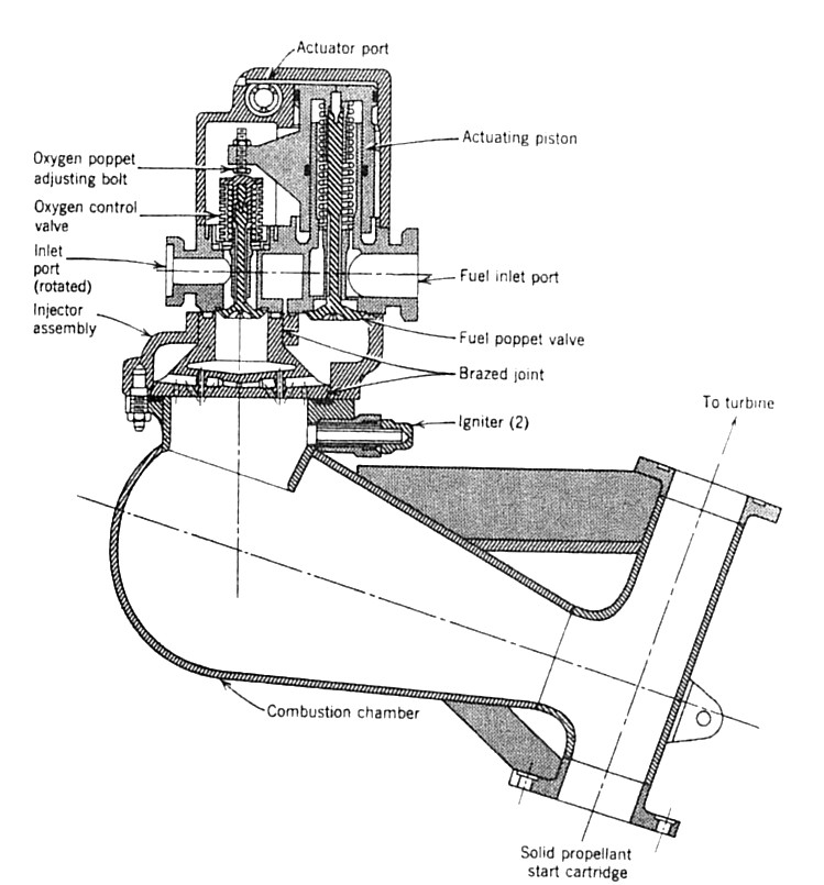
SATURN I/IB First Stage (S-I/S-IB) H-1 Rocket Engine Liquid Propellant Gas Generator (LPGG) which produced combustion gases during steady-state operation to drive the two-stage turbine, and drove a gear reduction train to power the H-1 propellant pumps (see following entry for an example of an H-1 Turbine Assembly). Propellants entering the LPGG were ignited by hot gases produced initially by a Solid Propellant Gas Generator (SPGG), which in tern ignited two squibless igniters prior to liquid propellant entry into the LPGG. Refer to the diagram at the left of this entry for a depiction of component location on the SPGG.
The LPGG incorporated a control valve which contained two poppets that admitted fuel (RP-1) and LOX propellants during engine operation. An injector provided a uniform mixture-ratio of .0341 (LOX/fuel). The injector cavity design permitted an oxidizer lead into the combustor during start to prevent detonation.
The gas generator injector (which can be seen in separate images to the left of this entry) is a uniform mixture-ratio type featuring two fuel streams impinging on a single oxidizer stream. From the injector, two fuel streams impinged on a single LOX stream via 44 impingement points. Fuel entering the combustor through 36 holes around the periphery of the impingements provided film coolant for the injector. The propellants then burned in the combustor and exited to the gas turbine.
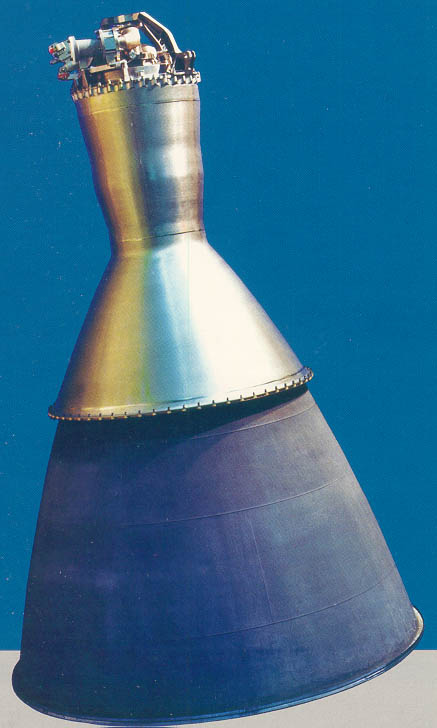
SATURN I/IB H-1 Bipropellant Rocket Engine
H-1 Turbine Lateral
H-1 Turbine Data Plate
Turbine 1st Stage Wheel
Exposed Turbine
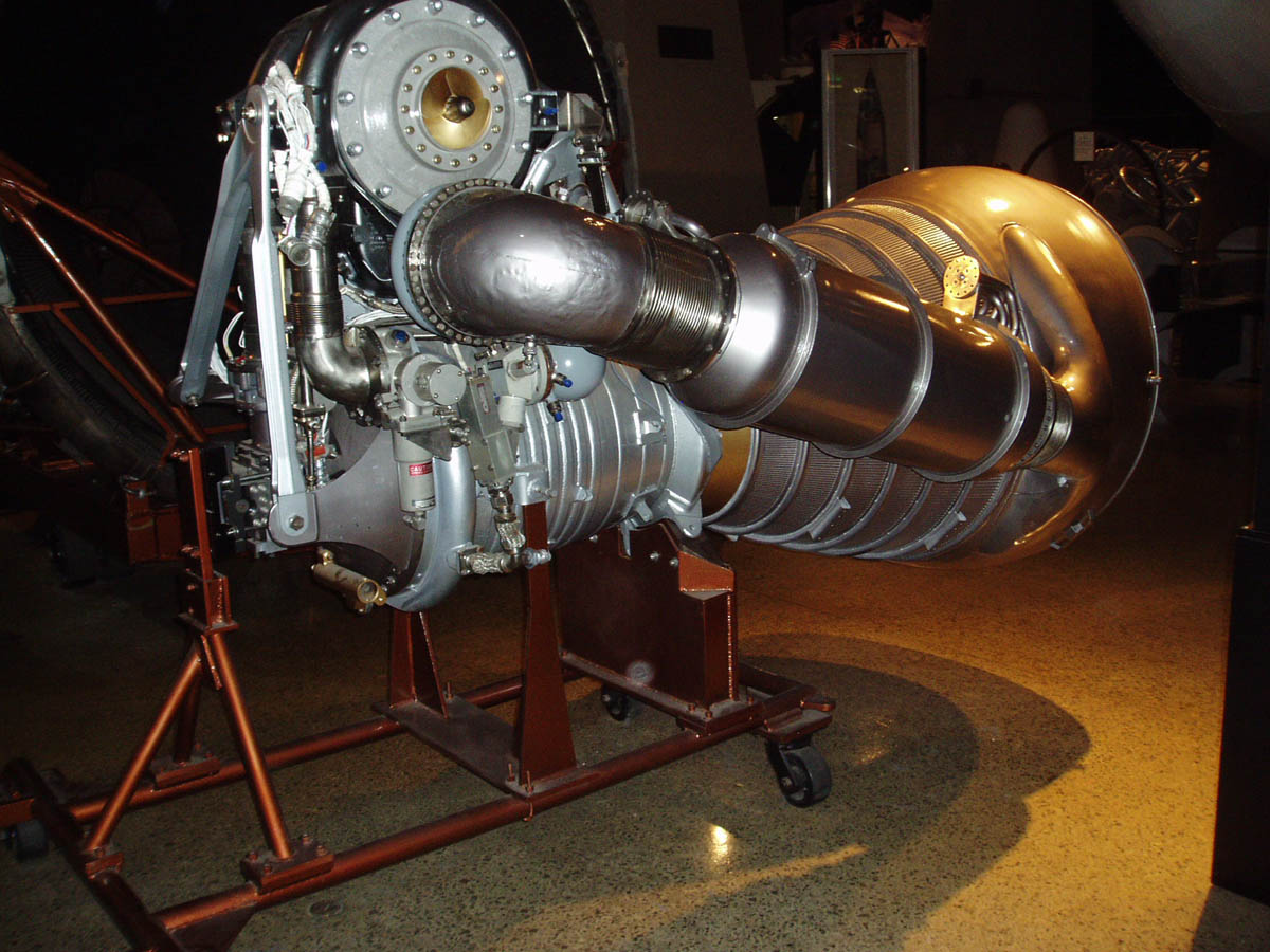
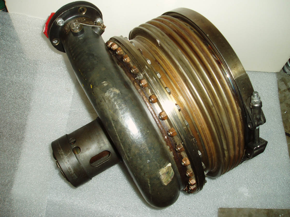
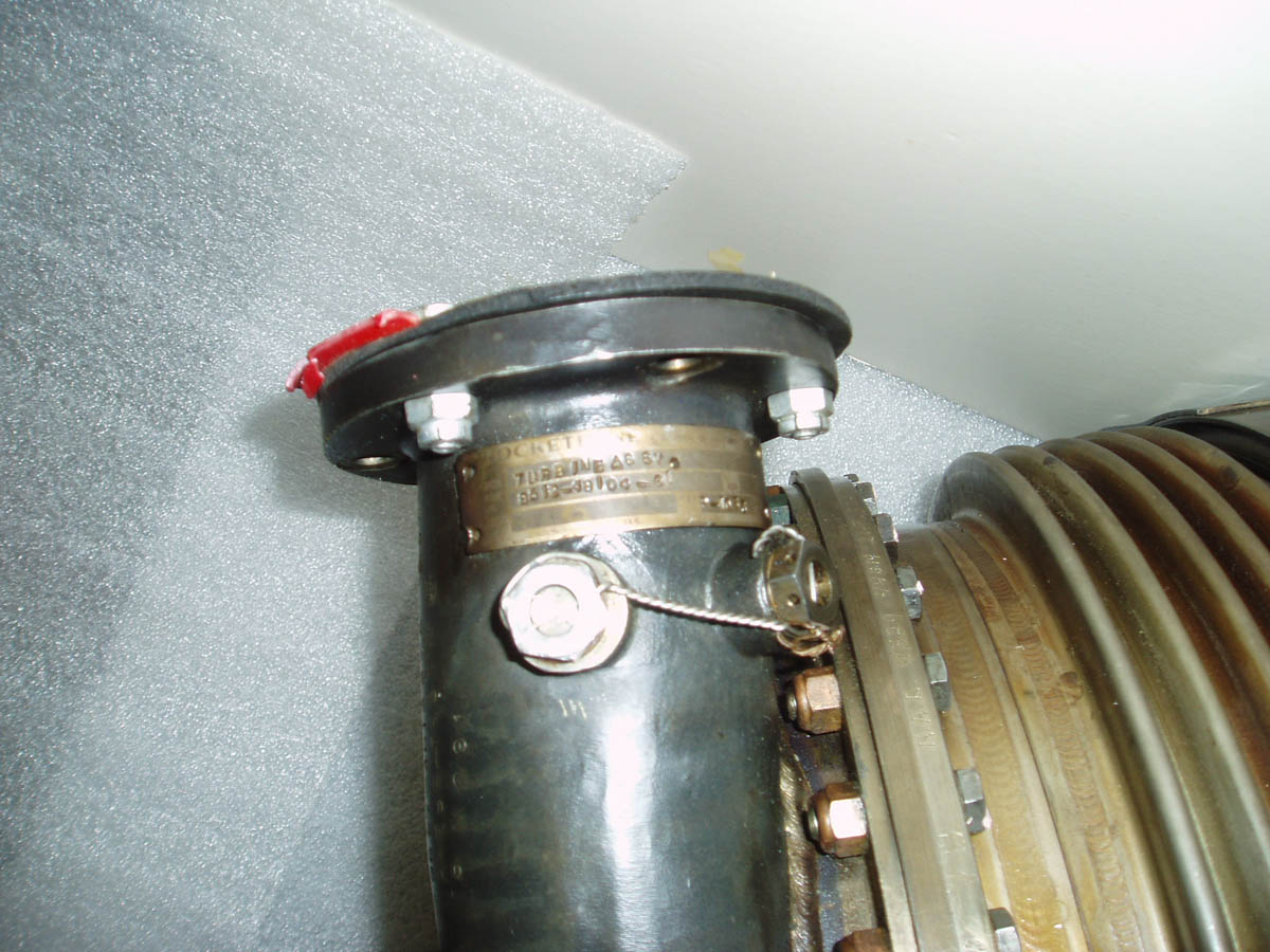
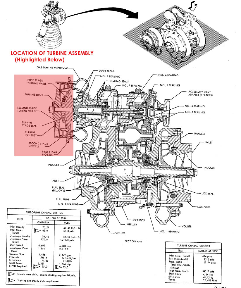
SATURN H-1 ROCKET ENGINE GAS TURBINE ASSEMBLY

SATURN I/IB First Stage (S-I/S-IB) H-1 Rocket Engine Turbine Assembly used to mechanically convert hot gases originated from the Gas Generator into rotational energy which was then transmitted through a gear box to drive the propellant (RP1 and LOX) pumps. It is an impulse, two-stage, pressure compounded unit that bolted to the engine fuel pump housing and consists of an inlet manifold, first- and second-stage turbine wheels and nozzles, a turbine shaft, and a splined quill shaft that connects the turbine shaft to the high speed pinion gear. The turbine shaft inboard bearing is a split race ball bearing, and the outboard bearing is a roller bearing. Carbon ring shaft seals prevent hot gas leakage into the bearings. Gases from the Gas Generator (an example of which precedes this entry) enter the gas turbine manifold and flow through the first stage nozzle to the first stage turbine wheel. The gases exhausted the turbine into the turbine exhaust system and ultimately into the H-1 thrust chamber exit flow. The turbine stage seal prevented the gases from bypassing the second-stage nozzle. An electrical tachometer using a single-element magnetic pickup sensed turbine shaft speed. This measurement was telemetered to ground receiving stations during flight and recorded for later evaluation of turbine performance.
Cut-Away of Complete H-1 Turbopump showing impellers and gearbox
Obverse View
Tag Data
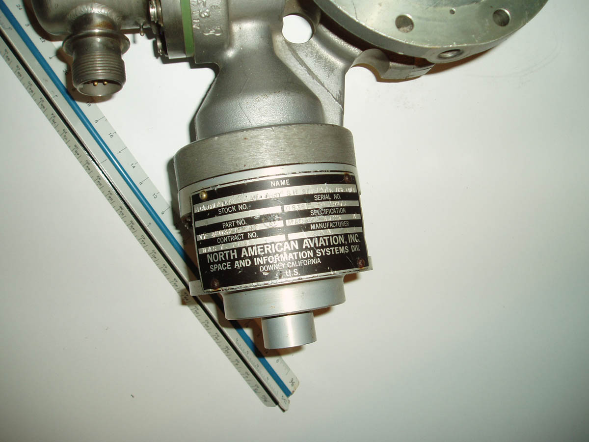
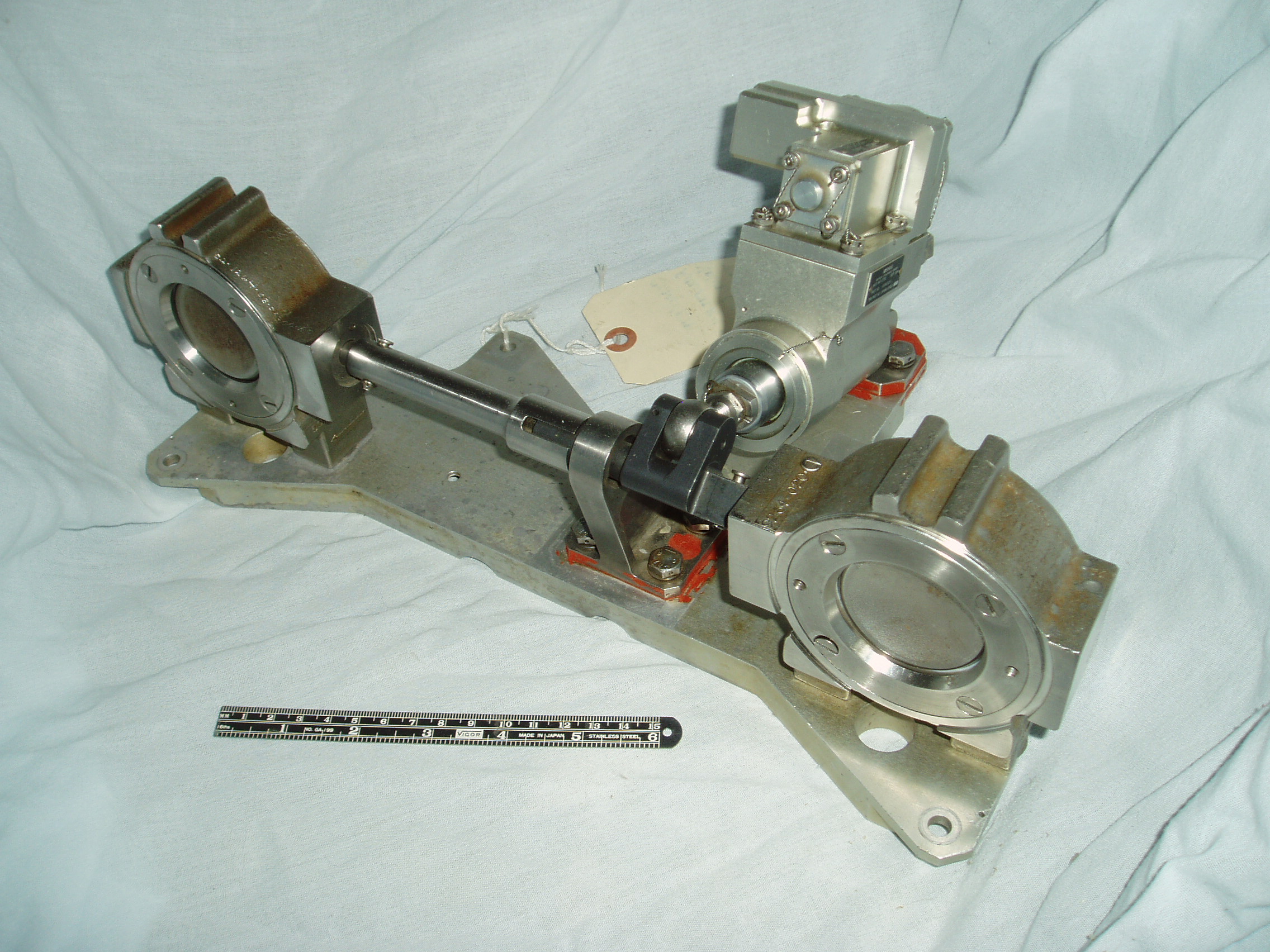
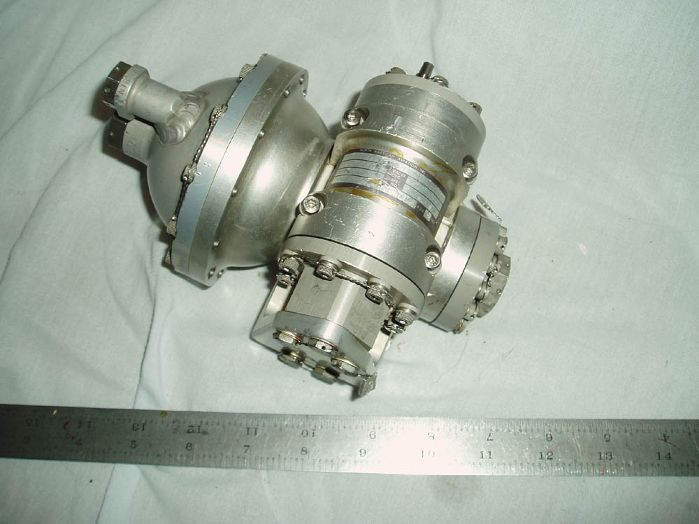
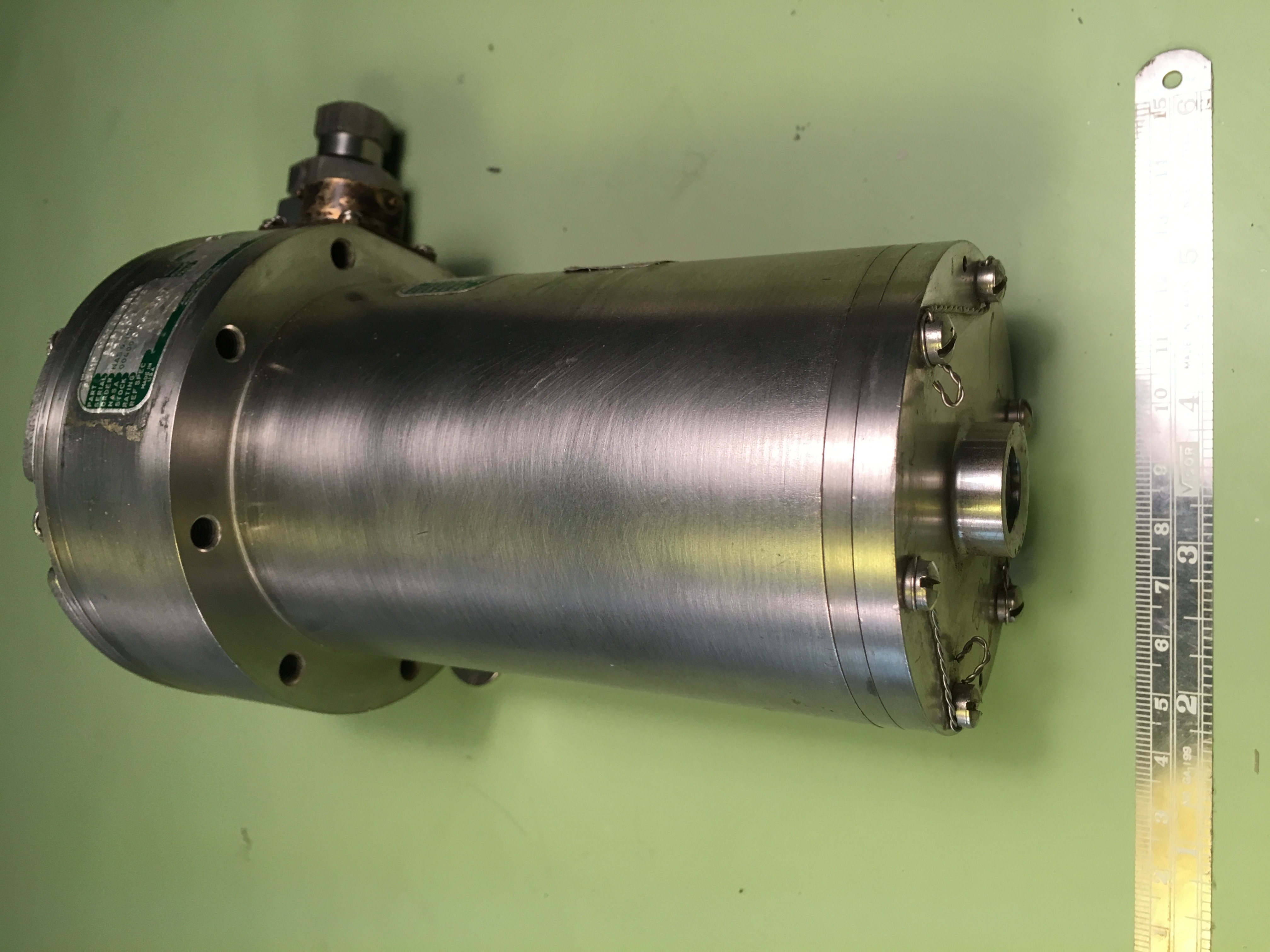
SATURN V SECOND STAGE VALVE
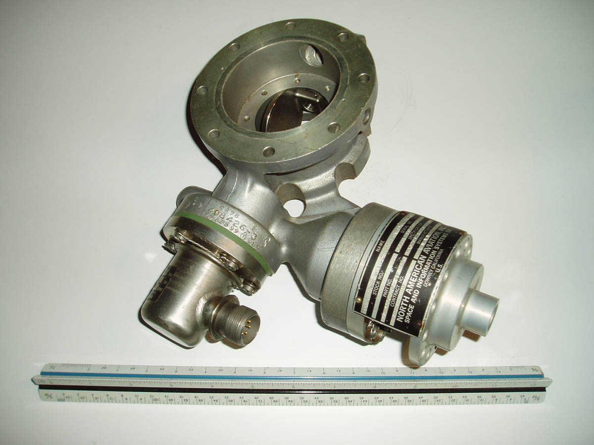
A Saturn V Second Stage (S-II) Recirculation System Valve Assembly manufactured by North American Aviation (primary contractor for the S-II). The valve, designed for the Liquid Oxygen (LOX) Recirc subsystem regulated propellant flow through the engine pumps. The subsystem, by keeping the propellants moving through lines, valves, and pumps, also ensures the parts remain chilled.
The LOX recirculation system worked on the basis of a thermal siphon; heat entering the system was used to provide pumping action by means of fluid density differences across the system. Helium gas was used to supplement the density differences and thereby improve the pumping action. Recirculation of oxygen began at the start of tanking; (LH2 recirculation begins just before launch). The propellants continue to circulate through first stage firing and up until just before the first stage and second stage separated.
J-2 Dome and Injector Assembly Cutaway
J-2 Injector Cutaway Detail
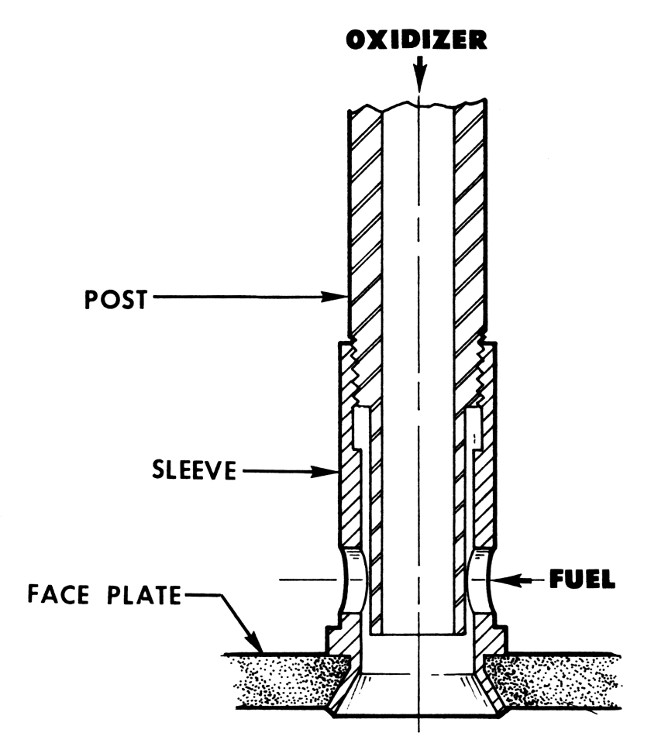
J-2 Injector Oxidizer Post
(Saturn IB Second Stage, Saturn V Third Stage)
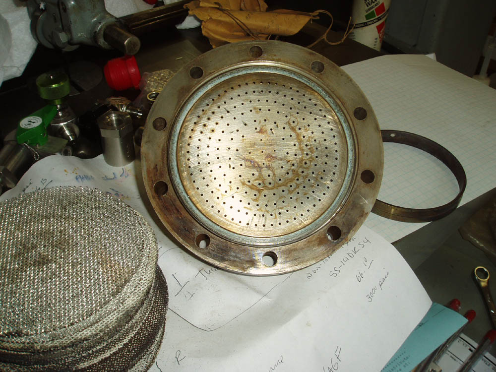
J-2 Injector Face Plate
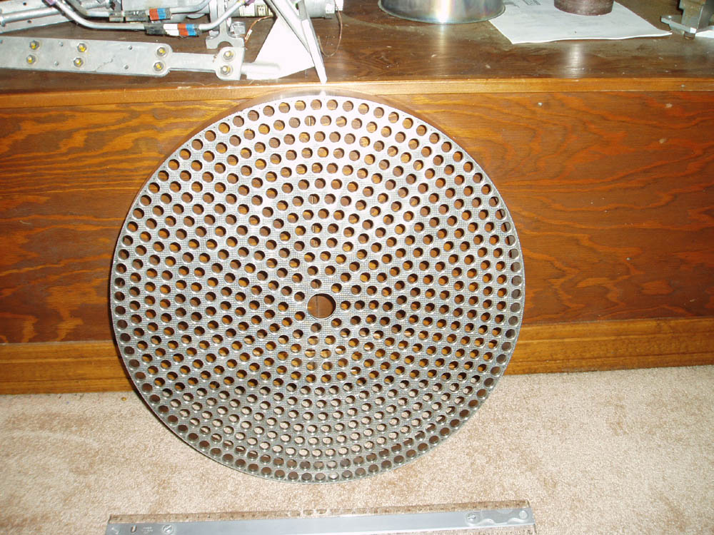
A J-2 rocket engine injector face plate, constructed of Rigimesh.
Rigimesh is a material constructed of layers of stainless steel mesh produced by a carefully-controlled sintering procedure which causes the layers of mesh to become a coherent structure without melting. Produced by the Pall Corporation, it originated as a filter used in nuclear research and had also been used other in environments subject to extreme vibration and high temperatures, such as the hydraulic and pneumatic filters in aircraft and jet engines.
Pratt & Whitney had used Rigimesh for the face plate of the injector in their RL-10 rocket engine. The porous face allowed a controlled flow of gaseous hydrogen to filter through, cooling the injector face and reducing thermal stresses. For the J-2, Rocketdyne initially tried a copper injector similar to those used in their LOX/RP-1 engines (such as the S-3D, H-1, and F-1). However, the heat fluxes of LOX-LH2 designs turned out to be much different at the injector face, and the injectors started burning out. At the direction of Marshall Space Flight Center, Rocketdyne switched to Rigimesh for the J-2, and the problems of injector face burning disappeared.
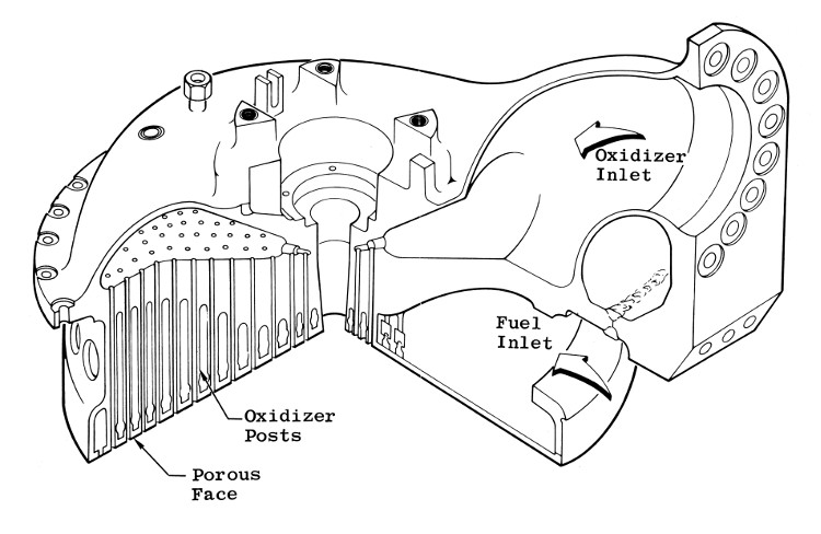
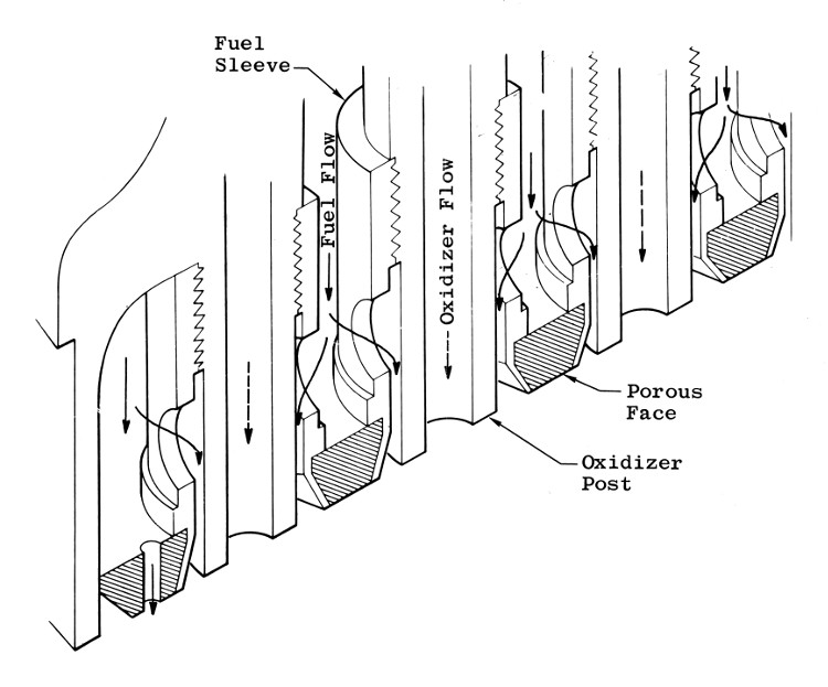
The overall injector was a flat-faced, concentric-orificed injector with a porous Rigimesh face. Six hundred fourteen oxidizer posts were machined to form part of the injector, with fuel nozzles threaded and installed over the oxidizer posts and swaged to the face of the injector. The resulting injector face was welded at its outside and inside edges to the injector body.
An oxidizer inlet elbow was an integral part of the dome and injector assembly. The injector received liquid oxygen through the oxidizer inlet elbow and injected it through the oxidizer posts into the combustion area of the thrust chamber. The fuel was received from the upper fuel manifold in the thrust chamber and injected through fuel orifices which were concentric with the oxidizer orifices. The propellants were atomized and mixed in a manner to produce the most efficient combustion. The Rigimesh forming the face of the injector allowed three or four percent of the fuel to flow through and cool the face of the injector.
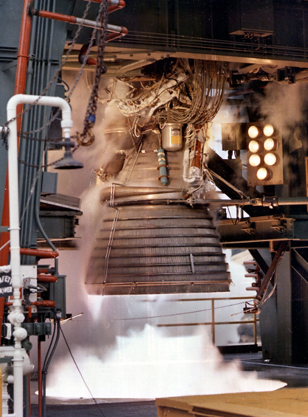
J-2 Test Fire
Rigimesh was later used in the Space Shuttle Main Engine (SSME) and M-1 rocket engine injector face plates as well.
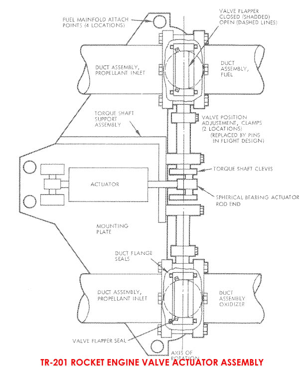
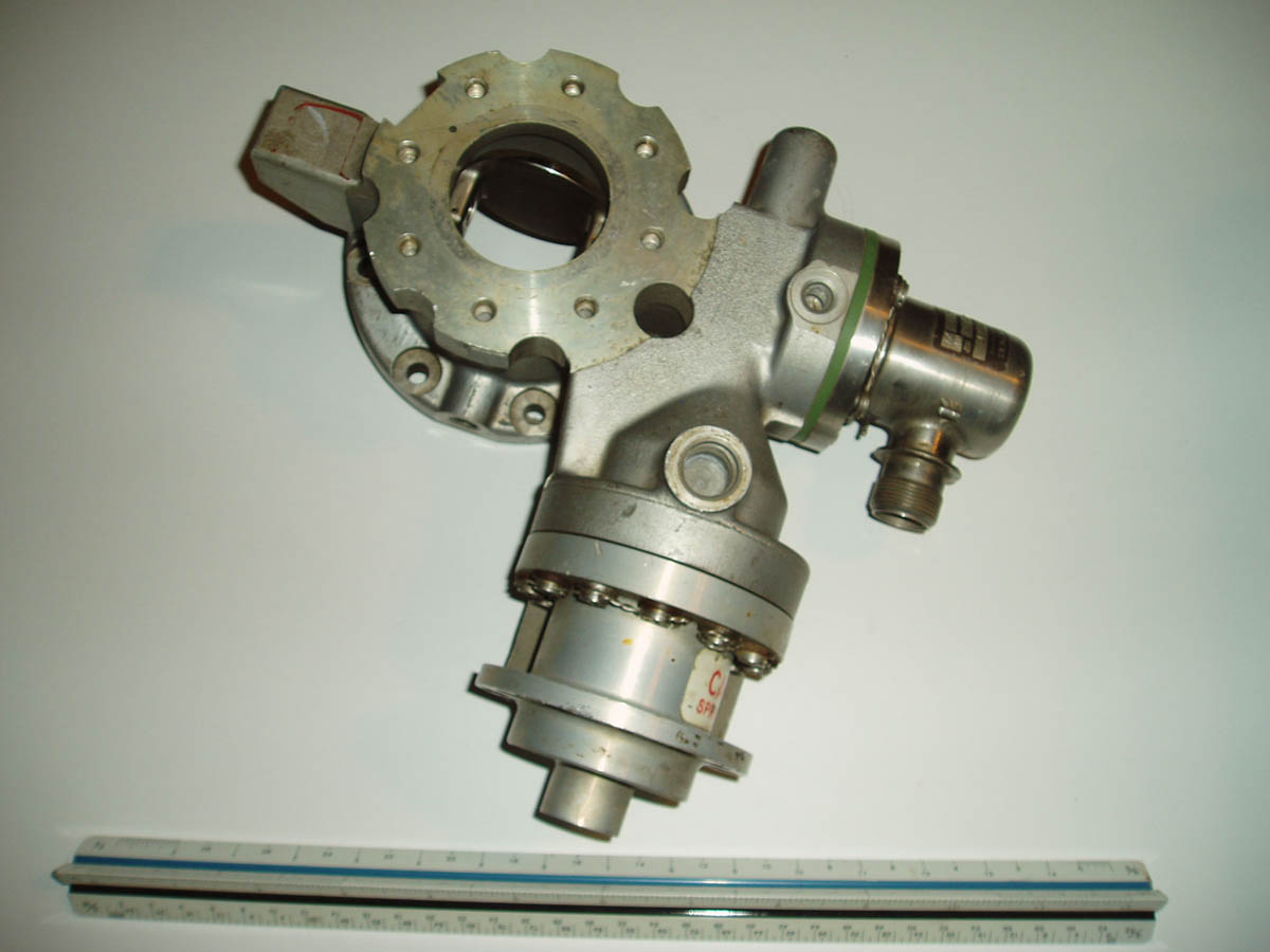
Actuator Valve Sub Component Breakdown
TR-201 Actuator Valve Assembly
TRW TR-201 Bi-Propellant Rocket Engine Tandem Actuator Valve Assembly which regulated the flow of Propellants (both fuel and oxidizer) into the thrust chambers Pintle injector. The two simple on-off butterfly type propellant vales are actuated in tandem on command by a single hydraulic actuator.
The major components of the actuator are the solenoid valve assembly and the hydraulic cylinder. The redundant coil solenoid is designed such that either coil is fully capable of operating the actuator in the event of electrical failure of one of the coils. To insure that the actuator remains closed without availability of supply pressure, a simple mechanical fingerlock is built in the hydraulic cylinder. The fingerlock engages the internal cam in the piston when the actuator is closed and disengages when the solenoid assembly applies supply pressure to open the actuator. The piston lock is spring loaded to return between the fingers when the actuator is retracted.
The internal seal of the propellant shutoff valve is a a highly reliable design compatible with both propellants (the TR-201 employed a hypergolic combination of nitrogen tetroxide and Aerozine-50 operating at a 1.6 mixture ratio). The seat design consists of two parts: a Teflon seal ring and an elastomer backing o-ring. The I.D. surface of the seal ring serves to effect a seal against the valve disc while its flange area securely locks the ring into a machined “T” slot within the valve body. When the disc is in the closed position, the backing ring preloads the seal ring against the disc affording a static seal. Propellant pressure along with the “T” slot creates a piston action of the seal ring amplifying the sealing force. The seal tightens as propellant pressure increased.
The TR-201 engine was a derivative of the Lunar Module Descent Engine (LMDE) and was employed as the 2nd stage engine on the Delta Space Launch Vehicle 2000 and 3000 series variants.
TRW TR-201 Bipropellant Rocket Engine
Injector
Catalytic Silver Screen
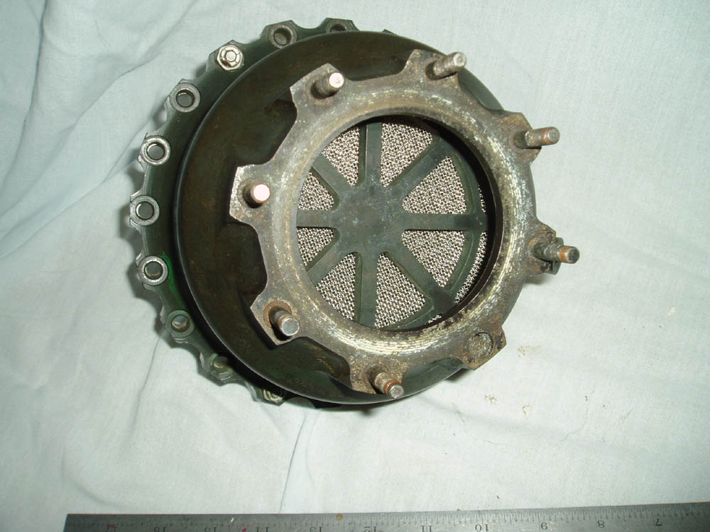
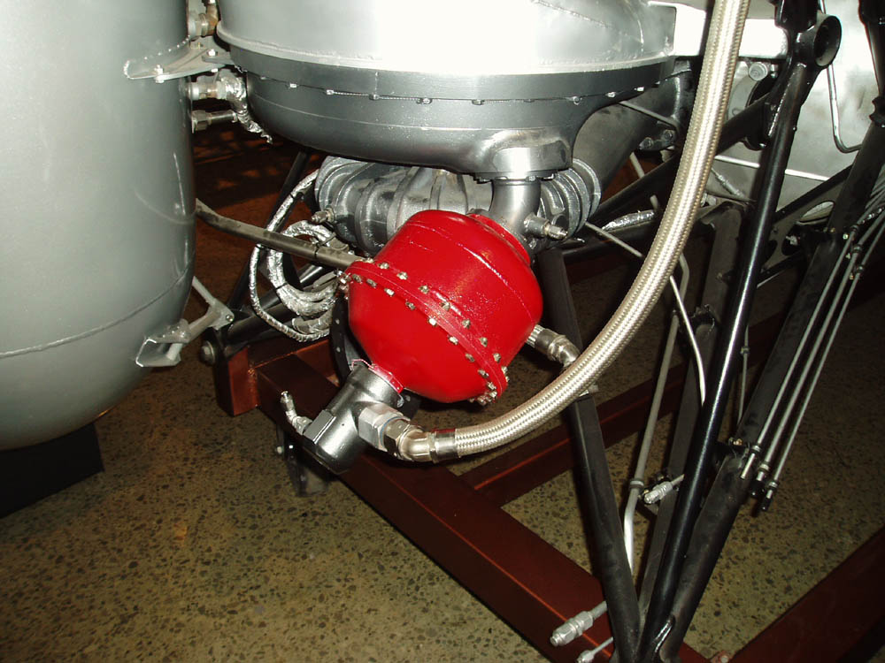
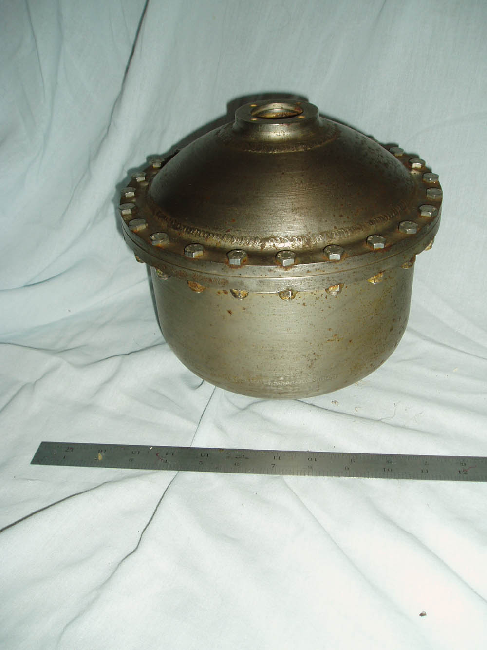
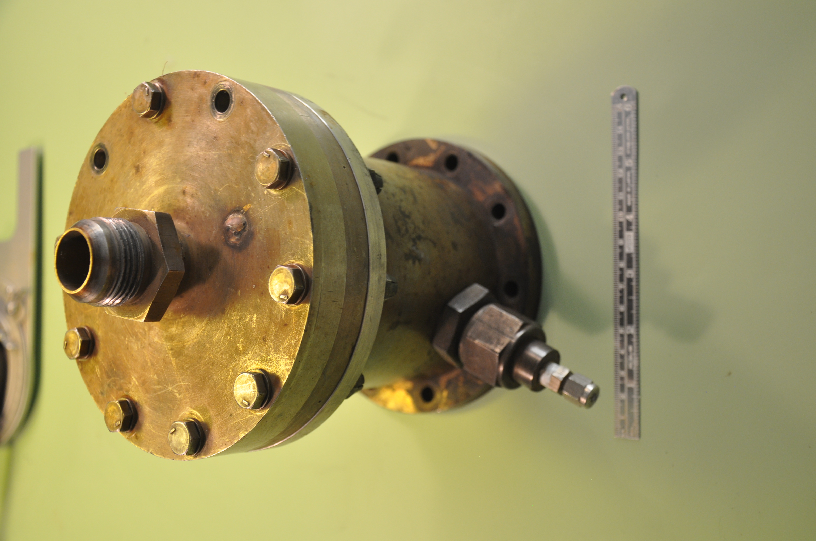
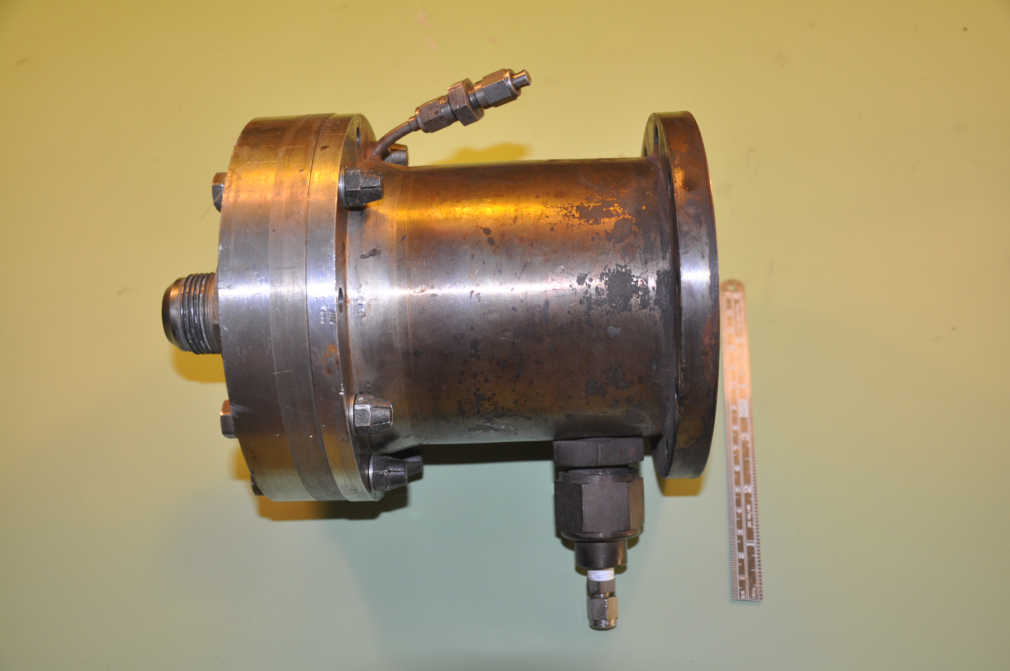
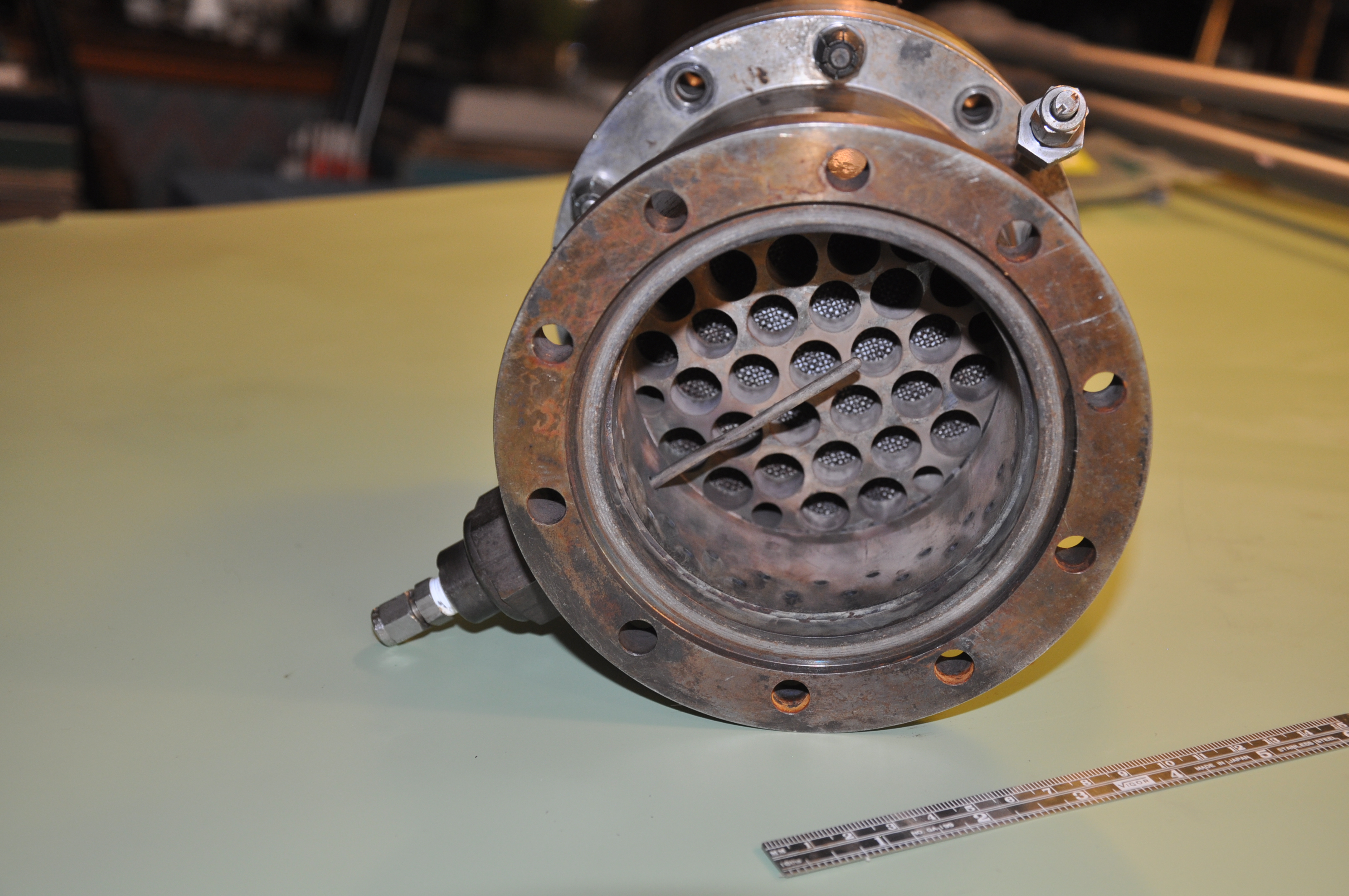
XLR-99 GAS GENERATOR
A Reaction Motors XLR-99 Gas Generator utilized to supply propellants to the X-15 Rocket Plane's main engine. The Gas Generator, part of the Turbopump assembly, converted Hydrogen Peroxide (passing the mono-propellant across a silver screen catalyst bed), decomposing the H202 into superheated steam and oxygen. The resulting gases drove the centrifugal turbine in the turbopump, which then operated separate compressors supplying ammonia and LOX propellants to the pressure fed XLR-99 rocket engine.
The catalyst bed consists of 35 activated silver plated screens alternately spaced between thirty six stainless steel screens. A stainless steel showerhead injector contained 415 holes is used to prevent channeling of the peroxide through the bed. The catalyst housing is Inconel X. The retainer plate (shown in the photo) is Waspalloy. The catalyst can decompose a throughput of 20 pounds per square inch per minute. The gas generator inner diameter is 5.75 inches.
Two gas generators were installed (one for each turbopump/propellant system).
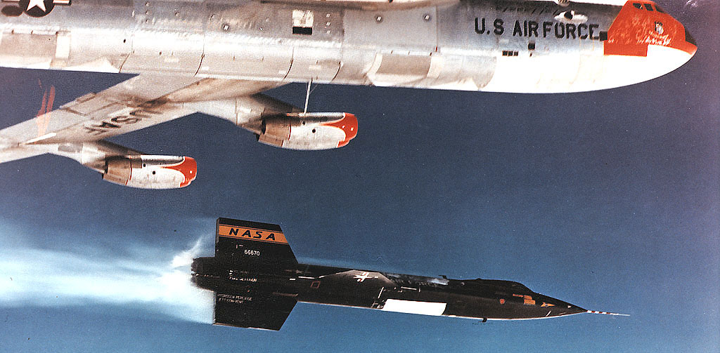
X-15 #1 (Tail 19770) B-52 Release
Helium Pressure Regulator
A North American Aviation (NAA) X-15A Helium Pressure Regulator which supplied 600 psi Helium (from four onboard 3600 psi source tanks). 600 psi helium was used to pressurize the turbopump Hydrogen Peroxide supply tank and to supply pneumatic pressure for XLR-99 engine and propellant control.
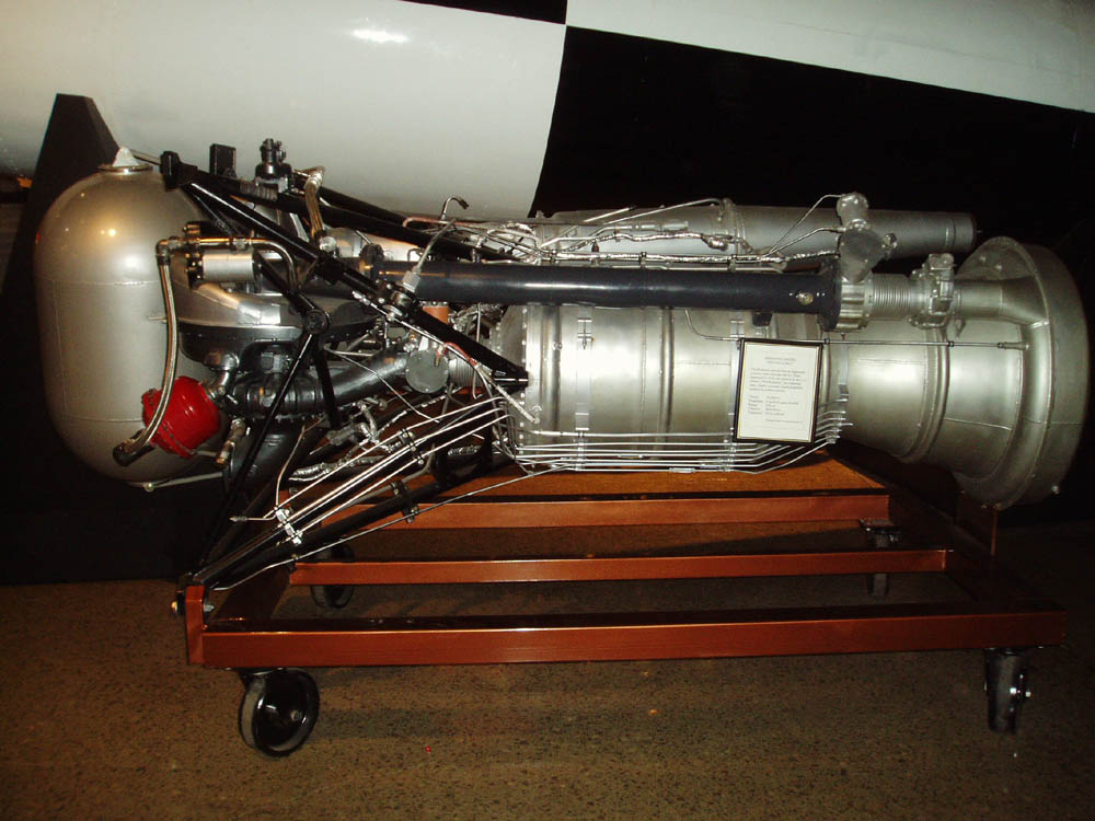
Redstone Engine
Redstone Gas Generator - Engine Location
Redstone Early Gas Generator
First generation Redstone engine gas generator. This prototype relied on catalytic decomposition of hydrogen peroxide across silver screens rather than the pellet bed mono-propellant configuration (silicon carbide permanganate impregnated "pebbles" - see following artifact for an A7 Redstone Production Gas Generator) used in the production Redstone engine.
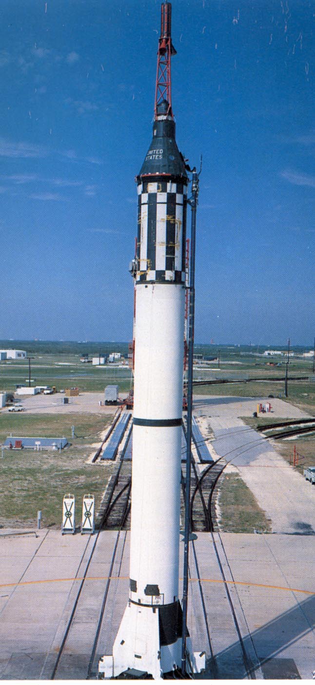
Mercury Redstone Manned Space Launch Vehicle
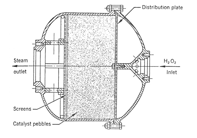
Gas Generator Schematic
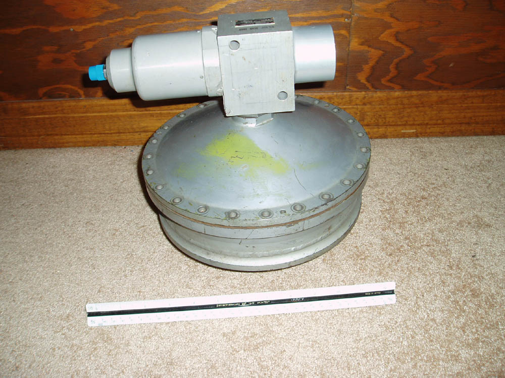
Redstone Production Gas Generator
A7 Redstone Bipropellant Rocket engine gas generator. This production gas generator used decomposition of hydrogen peroxide across a pellet bed of silicon carbide permanganate impregnated "pebbles" to drive turbines which fed propellant under pressure to the A7 injector.
Hyprox Prototype Steam Generator
Reaction Motors (RMI) prototype steam generator. These were used in a program called Hyprox aimed at military and civilian markets demanding high flow rate and instant steam demand at intermittent levels. Applications included altitude simulation, cryogenic sub-cooling, intermittent vacuum or steam ejector drives, and pilot-plant operations.
The steam generator used hydrogen peroxide and a silver screen catalyst, but injected fuel gas to burn with the oxygen to produce additional steam. These were used in vacuum generator systems for testing vacuum performance of rocket engines.
The operating sequence of production models would start with the introduction of a small quantity of hydrogen peroxide into the catalyst bed. After this preheating step, full peroxide flow would be initiated. The gaseous hydrogen was partially diverted through a pre-heat coil submerged in the decomposed peroxide steap, permitting spontaneous burning with the oxygen without ignition devices. Would would enter the unit through a cooling jacket and injected in sufficient quantity to generate the desired quantity of steam.
RMI Pinwheel "Rocket on a Rotor" Rocket Motors
Reaction Motors hydrogen peroxide "rocket on a rotor" rocket motors.
I believe these were prototypes for the tip jet powered autogyro program called Pinwheel. These were located on the tips of the autogyro blades and used to power the blade rotation. This program occurred around 1954. The motors appear to be sized to produce between 15 to 20 pounds of thrust. Further work was done by RMI to provide power using tip rockets for Sikorsky helicopters to aid high altitude operation.
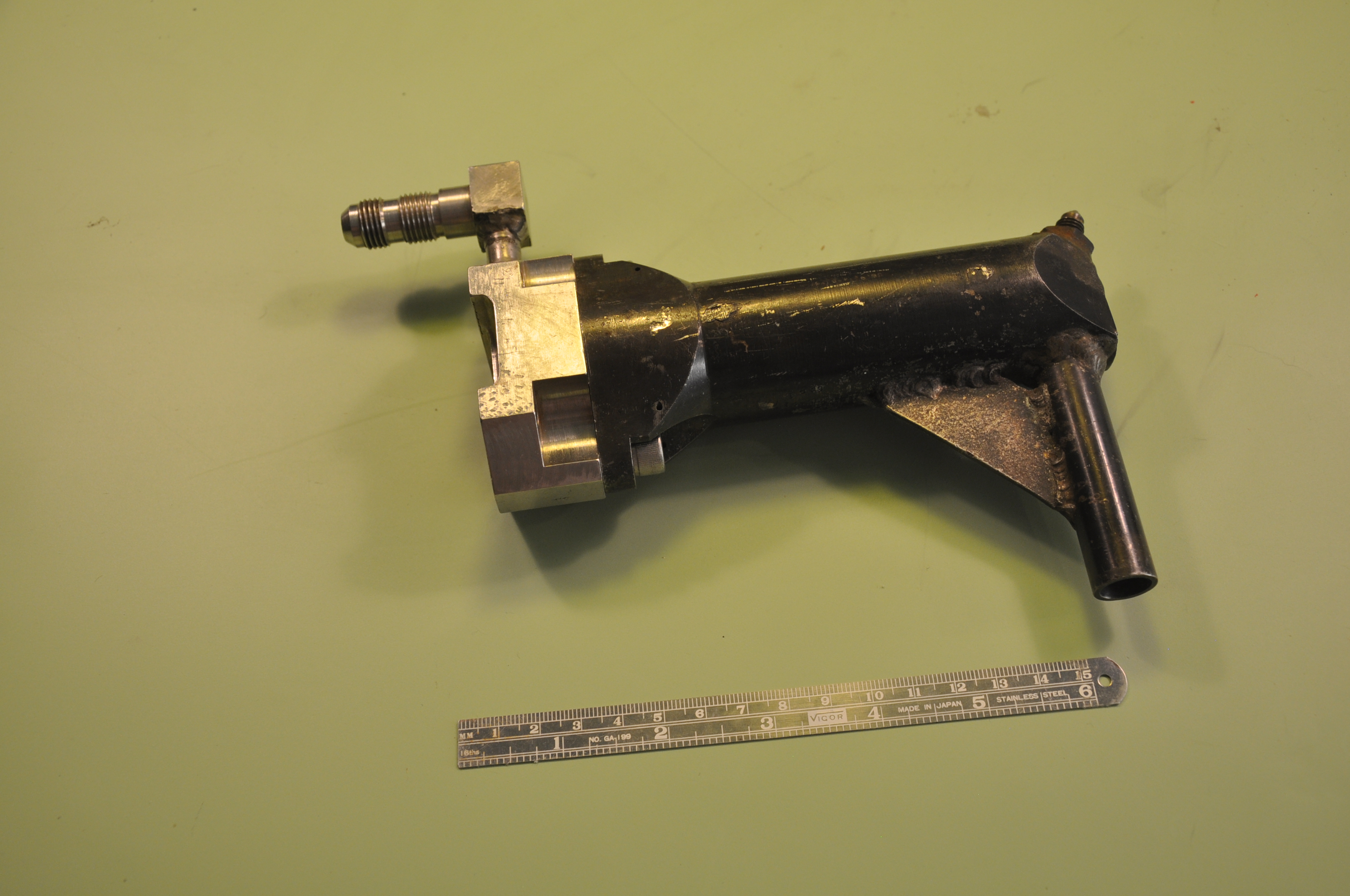
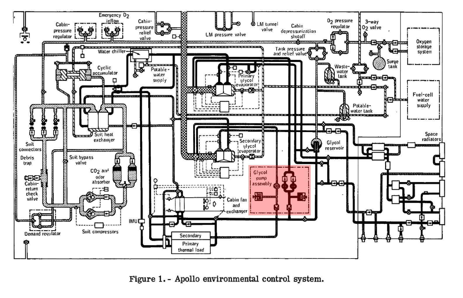
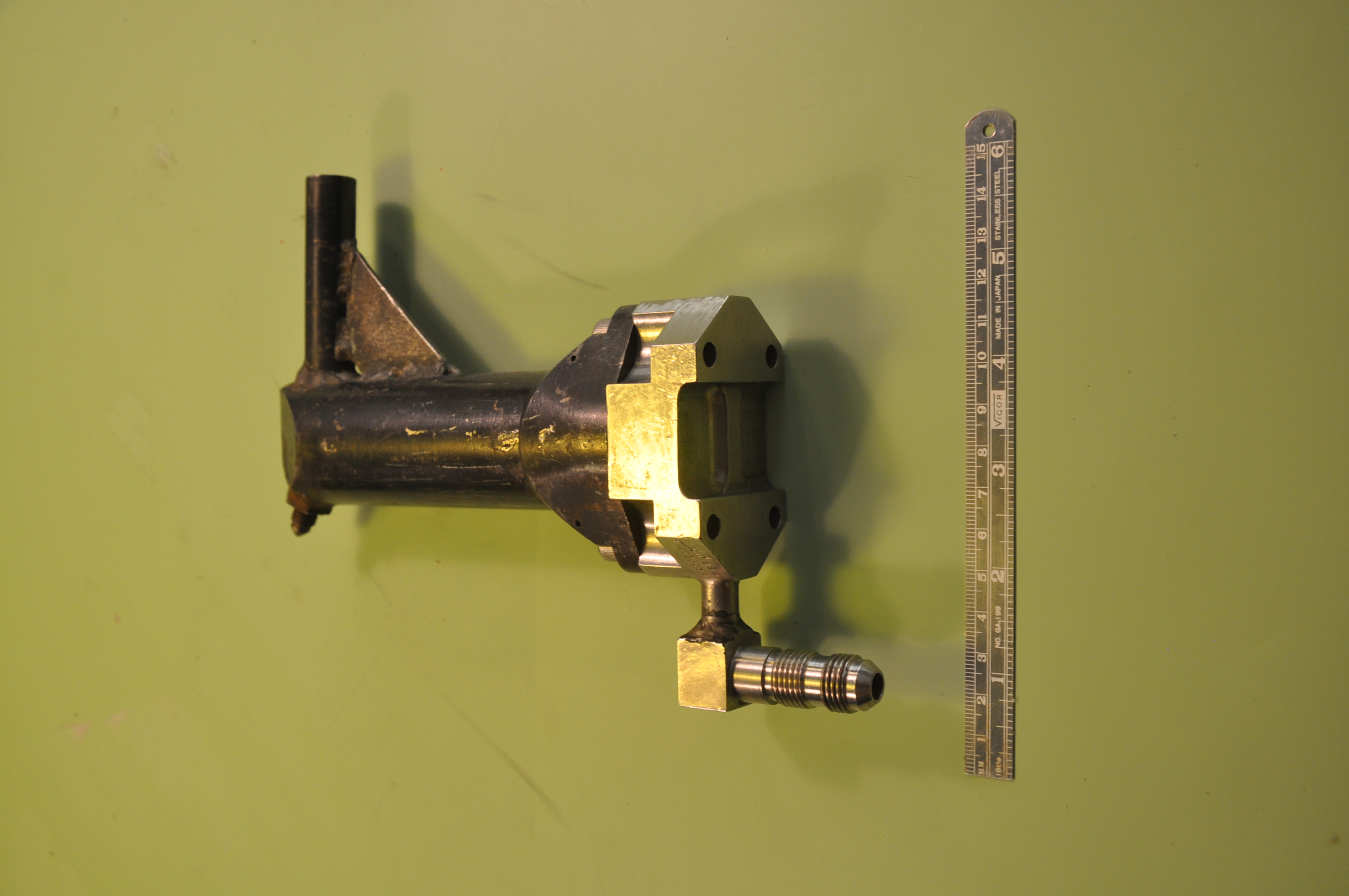
Apollo Environmental Control System
Apollo Command Module Water Glycol Pump
Apollo capsule liquid coolant pump.
This pumped a water-glycol mix that was used for cooling the capsule. There were two of these pumps and were used to control the cabin and suit temperature and also to cool some devices.
Solid Rocket Booster Parachute Line Cutter
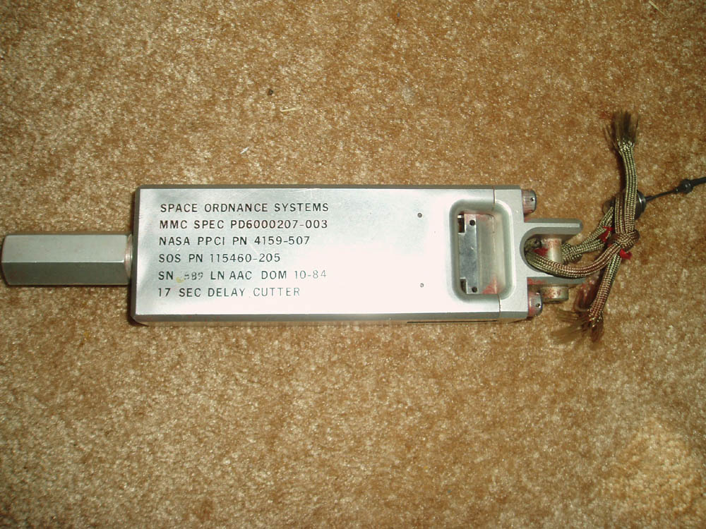
This flown pyrotechnically actuated cutter was used to sever a "reefing line" on the Solid Rocket Booster's 54 foot diameter drogue parachute. Several of these were used to sequentially cut the reefing lines used to keep the skirt of the drogue gathered together for a controlled release (at 60, 80 and finally 100% inflation). The gradual expansion of the canopy was necessary to reduce the shock of aerodynamic braking on the parachute fabric.
The drogue was responsible for slowing the SRB's rate of descent to a velocity of 250 mph; at 9800 feet the 3 primary chutes were deployed.
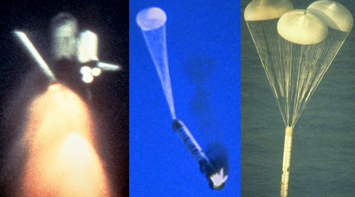
SRB Drogue and Primary Canopy Deployment
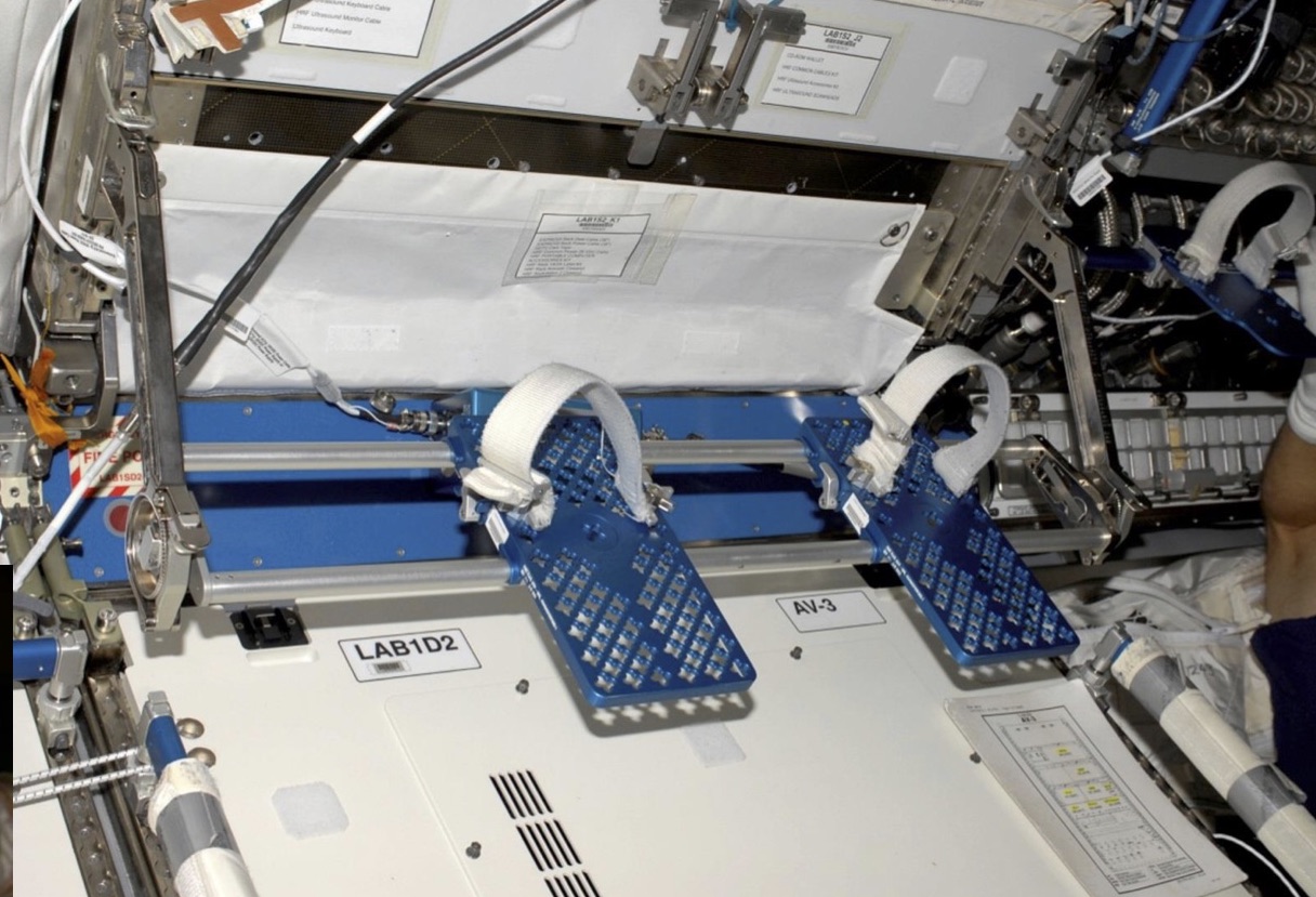
Long Term Foot Restraint installed on ISS
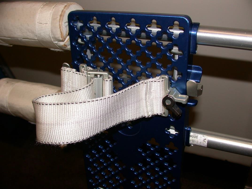
Foot loop assembly on Long Term Foot Restraint foot plate
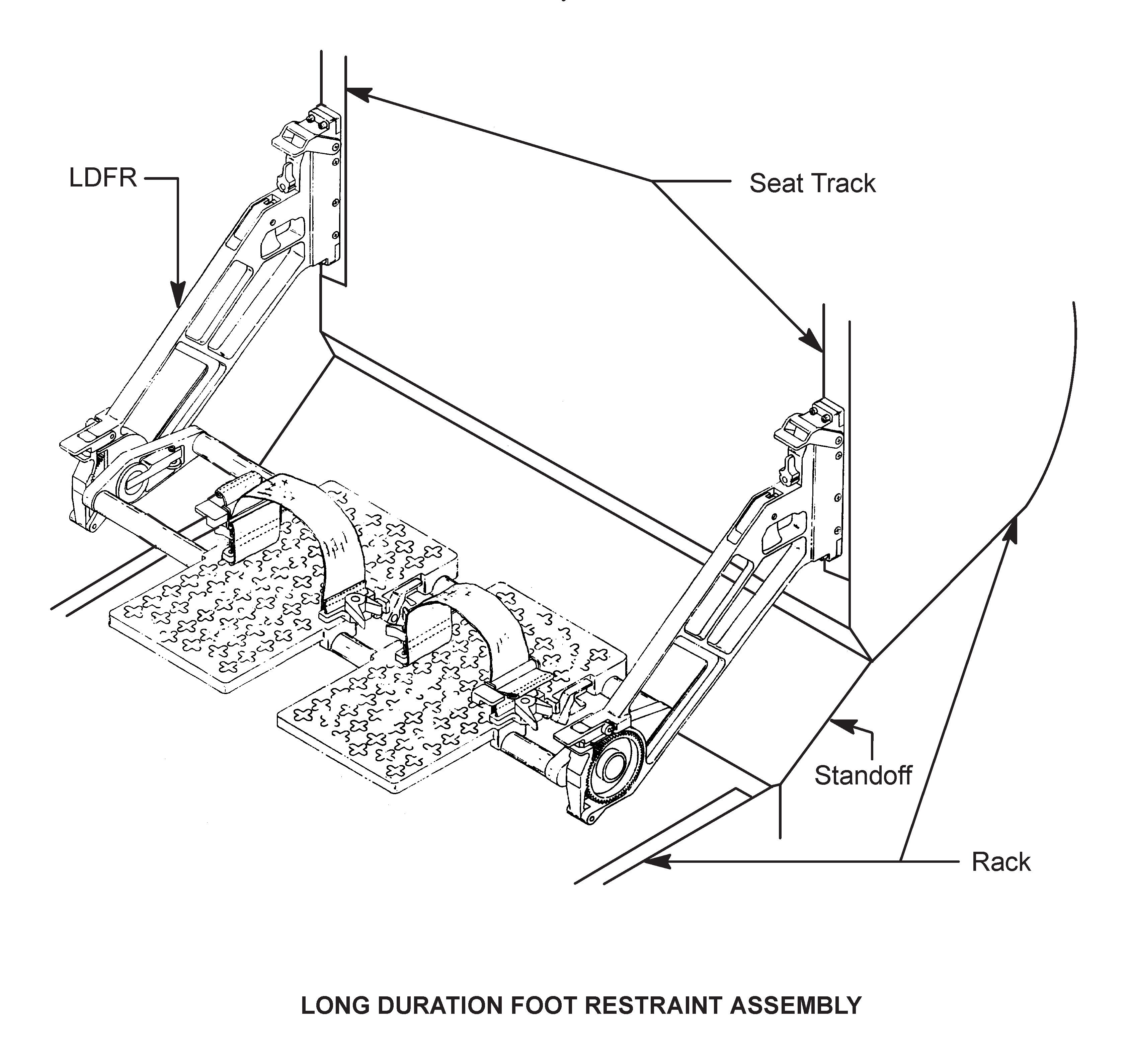
Long Term Foot Restraint diagram with callouts
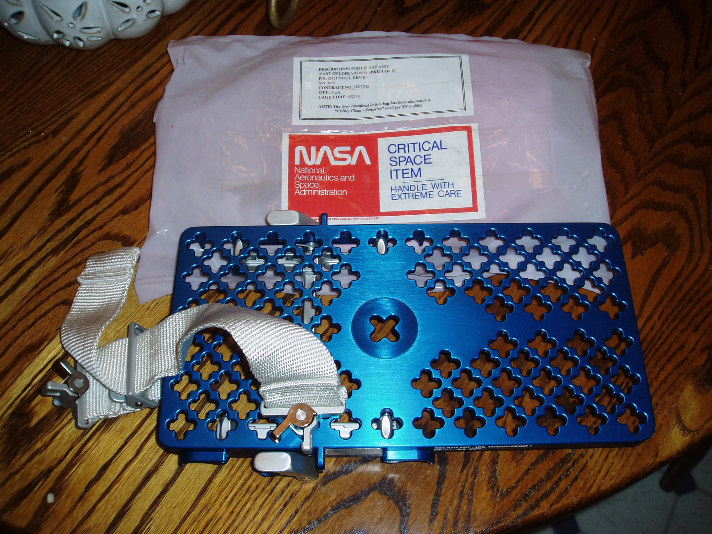
International Space Station Long Duration Foot Restraint Foot Plate
Top of Long Term Foot Restraint Assembly.
A foot plate from an ISS Long Duration Foot Restraint (LDFR).
LDRFs are installed at double–wide rack work stations where crew members might stay restrained for long periods of time. This contrasts with the Short Duration Foot Restraint (SDFR), which provides "fly–in" and "fly–out" foot restraint for those worksites which the crew might frequently visit but typically remain at for less than 10 minutes.
The LDFR consists of one left and one right brace assembly, one rail assembly, two identical foot plate assemblies, and two foot loop assemblies. Once installed at the worksite, the LDFR can be moved up and down the rack’s seat track for height adjustment. Foot plate pitch adjustment of 360 degrees is provided and the foot plates may be located anywhere along the length of the rail assembly in order to provide the crew member with stance and worksite centering adjustments. The rail assembly and the foot plates can be reversed when additional standoff distance from the rack face is required.
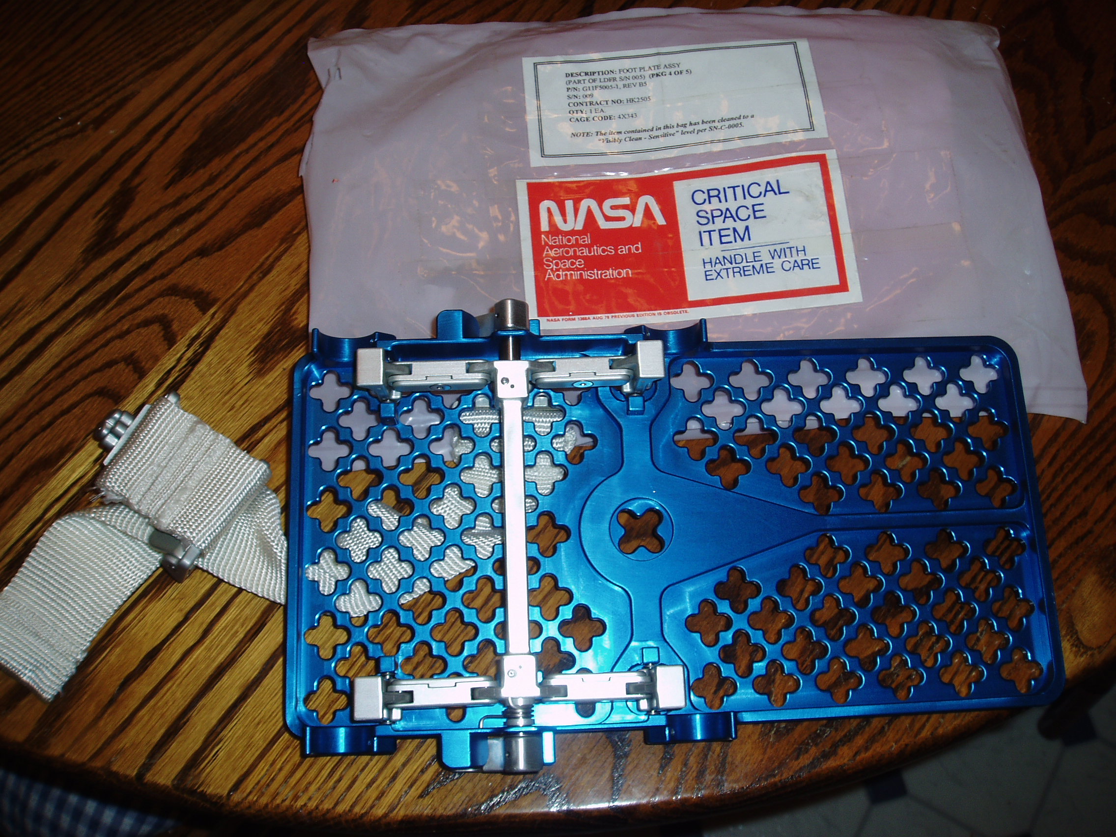
Bottom of Long Term Foot Restraint Assembly.